
High-power EV and EVSE tester
Test vehicles and chargers under real power in your own lab.
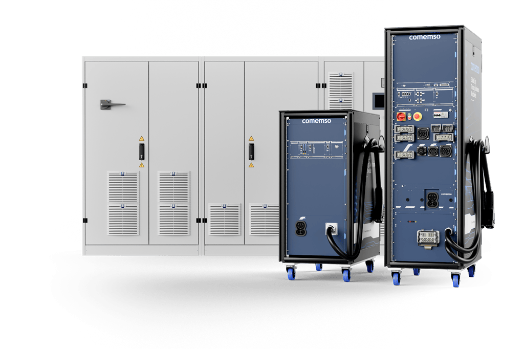
EVCA Flex simulates the charging station or the vehicle. It combines communication, signals, external power equipment and fault modules in one laboratory setup – instead of separate sources, loads and analysers.1
Up to 1,500 V and 500 A as standard – 600 A or 800 A on request.
- What for
- Laboratories that test vehicles or chargers under real power.
- What it does
- Up to 1,500 V and 500 A as standard, 600 A or 800 A on request. EV or EVSE simulation, external power equipment and fault modules in one setup.
- Not for
- Installation checks in the field – that is Easy Chester; megawatt truck charging – that is EVCA MCS.
A high-power charging fault that first shows up at a customer's site means damaged hardware and lost trust.
EVCA Flex at a glance
Published Flex voltage, current and fault configurations
| Parameter | Published scope | Configuration condition |
|---|---|---|
| CCS / NACS voltage | Up to 1,500 V. | The selected interface and complete system define the final voltage range. |
| Charging current | Up to 500 A standard; 600 A or 800 A on customer request. | Customization, voltage, duration and cooling must be specified together. |
| Short-circuit configuration | Up to 1,000 V / 500 A. | Only the approved fault topology, hardware, energy limits and operating conditions apply. |
| Actual operating point | External source, load or bidirectional power system. | Power, continuous and peak duration, cooling, switching energy and facility limits are confirmed for your project. The listed maxima do not establish a continuous power rating. |
Your Flex configuration
The standard sets the test requirements; we agree hardware, software release and test cases for the delivered system on that basis.
Text updated:
One platform tests both sides of the charging interface.
EV testing with EVSE simulation; EVSE testing with EV simulation

The vehicle, tested against EVSE simulation
EVSE (charging station) communication, low-level states and the selected source work together. EVCC (vehicle-side charging communication controller), charging inlet, onboard systems and the complete vehicle are tested under controlled conditions.
- AC and DC EVSE simulation
- Source and grid-emulator integration
- EVCC, battery management system (BMS), OBC and vehicle-state correlation
- Conformance, robustness and regression campaigns
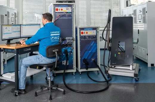
The station, tested against EV and battery simulation
EV communication and battery requests drive the selected load or bidirectional supply and the released fault modules for charger development and verification.
- Configurable EV and battery behaviour
- Load or battery-emulator integration
- Output control, protection and shutdown reaction
- IEC 61851-23 and project-specific electrical testing
Modular system architecture
Flex test architecture: simulation, charging interface, power and analysis
Replace or expand rack and cassette hardware without returning the complete test environment when connectors, standards, voltage classes or test objectives change.

You choose protocol, low-level states, connector and operating behaviour for the DUT.
Connector, voltage class, current path and measurement channels follow the project.
Power equipment and fault hardware integrate without changing the charging-specific software workflow.
comframe configures the test, analyses the charging event and automates supported sequences. comframe keeps complete session records for review.
EVCA Flex with the IEC 61851-23 rack
Provoke the electrical fault. Measure how the EVSE responds.
EVCA Flex with dedicated IEC 61851-23 switching and fault hardware addresses the full Annex CC.7.5 test scope in the matching system configuration. comemso demonstrated these test cases on a customer’s charging station in its own laboratory.
| Test element | Configuration and observation |
|---|---|
| Real DUT and setup | A DC charging station is the DUT. EVCA Flex simulates the vehicle; the selected external load or bidirectional system covers the planned charging condition. |
| Configured fault | Use the approved short-circuit hardware path and test sequence for the selected operating point. Confirm voltage, current, fault energy, protection and switching scope before the test. |
| Observed response and verdict | Record the fault trigger, charging communication, voltage and current waveforms, and the EVSE protection or shutdown response. Compare the captured response with the acceptance criteria of the applicable test case. |
| Measurement and software | Specify oscilloscope channels, probes, bandwidth and trigger with the TestLib. The existing IEC 61851-23 demonstration used CANoe; its comframe port is not yet released. comframe remains available for the separately released simulation and analysis functions. |
Illustrative test objective for planning your configuration. We define the electrical fault path, measurement equipment and operating conditions for the approved setup.
Short-circuit configuration · Current IEC TestLib workflow · Synchronised test-action and response analysis
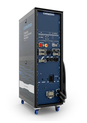
Charging simulation, interfaces, synchronised measurement, power coordination and comframe.

Dedicated switching and fault paths for the selected released test scope.
Test setup and responsibilities
| Test function | Primary system element | Project definition |
|---|---|---|
| EV simulation and charging communication | EVCA Flex and comframe | Charging family, protocol edition, certificates, messages and low-level behaviour |
| Voltage, current and power coordination | EVCA Flex with external source, load or bidirectional system | Operating quadrant, dynamics, maximum and continuous envelope, cooling and facility limits |
| Selected IEC 61851-23 electrical paths | IEC 61851-23 rack where required | Released switching and fault modules mapped to the applicable test cases |
| Waveform acquisition | External oscilloscope and measurement equipment | Channels, probes, bandwidth, trigger conditions, isolation and data handover |
| Test sequence and verdict | IEC 61851-23 TestLib; CANoe in the demonstration | Standard edition, annex, Test Library release, project parameters and report requirements |
| Power absorption | External load or bidirectional power system | The load must cover the charger power required by the planned test condition |
Agree fault cases, voltage, current, power, switching and protection, source or load, measurement channels and TestLib version. Then assess your EVSE in the demonstrated laboratory setup.
Discuss the test scope and demonstrationSynchronised records of communication and electrical behaviour
Fault-response analysis: trigger, communication and electrical measurements
EVCA Flex and comframe put communication signals, electrical measurements, fault commands and DUT responses on a common time base. The test compares the response with the test requirement, and controlled tests confirm the suspected cause.
- High-level communicationMessages, sequence, timing, TLS and certificate context.
- Low-level interfaceCharging states, connection conditions and released signal measurements.
- Power behaviourRequested and measured voltage, current, source or load response and shutdown.
- Test actionFault trigger, switching command, test step, expected condition and actual reaction.
comframe relates measurements and protocol events to expected limits and highlights deviations automatically.
Supported message content, timing and deliberately nonconforming partner behaviour are configurable.
Versioned procedures run with automated steps, verdicts and reports according to the scope.
Saved charging cycles, variants, endurance sequences and unattended campaigns run automatically.
Field to labThe system reproduces supported field behaviour actively at the physical charging interface.
Supported source, load, HiL and automation systems work together while the charging-domain workflow stays the same.
Charging standards and product selection
AC and DC charging tests with EVCA Flex. Dedicated MCS testing with EVCA MCS.
AC and DC charging
IEC 61851-1, IEC 61851-23, DIN 70121, ISO 15118 including applicable ISO 15118-20 scope, SAE J1772 and selected NACS interfaces.
CAN-based DC charging
EV and EVSE simulation, communication analysis, measurement and Test Libraries according to the supported release.
Chinese DC charging
GB/T 18487.1 and GB/T 27930 variants according to the selected product and project configuration.
Megawatt Charging System
EVCA MCS covers 10BASE-T1S, MCS low-level states, cooled interfaces and megawatt power integration in its dedicated MCS test architecture.
View EVCA MCSApplication first
When does an end-of-line test need EVCA Flex?
Easy Chester covers repeatable production acceptance. EVCA Flex fits when your acceptance plan calls for laboratory power integration, advanced electrical conditions or controlled fault tests.
The delivered system, planned with you
Flex configuration: device under test, interfaces, external power and test scope
Work with the application engineers to define Flex, IEC-rack, external-power and software scope. Agree supplied and external equipment, safety responsibilities and the integration tasks of each party.
EV, EVCC, complete vehicle, EVSE, SECC (station-side charging communication controller), power module or charging subsystem.
AC, CCS, NACS, CHAdeMO or GB/T, including regional connector and protocol variants.
Voltage, current, operating quadrant, continuous and peak power, dynamics, cooling and facility constraints.
Protocol, signals, switching, short circuit, standard edition, annex, Test Library and required IEC-rack paths.
Voltage, current, oscilloscope channels, trigger, time base, reports and data handover.
comframe licences, APIs, external systems, campaign throughput, training, maintenance and future expansion.












“Currently the best and most complete vehicle simulator / sniffer / man in the middle we have used.”
Frequently asked questions
EVCA Flex and IEC 61851-23 FAQ
What is EVCA Flex?
EVCA Flex is a modular high-power laboratory system in the comemso EV Charging Analyzer/Simulator platform. It combines charging communication, low-level signals, measurement, external power integration, configured fault functions and comframe for EV and EVSE development.
Can EVCA Flex test both electric vehicles and charging stations?
Yes. For EV testing, it represents the charging-station side and coordinates the selected source and interface. For EVSE testing, it represents the vehicle and battery side and coordinates the selected load or bidirectional system.
Is the IEC 61851-23 rack included in every EVCA Flex system?
No. The IEC rack is an additional hardware path for selected electrical verification tests. A communication, development or general high-power Flex configuration does not automatically include it. The project scope must define the applicable test cases, switching paths and external measurement equipment.
Which IEC 61851-23 annexes are relevant?
IEC 61851-23:2023 has one annex per system: AA for System A (CHAdeMO), BB for System B (GB/T DC) and CC for System C (DC CCS). Further general annexes complete it. The delivered system and Test Library must state which annex and test cases are released. The current combined Flex and IEC-rack project path is positioned primarily around DC CCS Annex CC verification.
Customer projects, success stories and technical articles related to this page.
- Customer projectEVCA Flex for Certification LaboratoriesThe 350 kW-class EVCA Flex configuration supports repeatable charging-station tests with defined CharIN test cases in a certification laboratory.
- Customer projectCCS EVSE Validation Before DeploymentCCS EVSE validation before deployment: a power provider tests charging behaviour and fault responses with 350 kW and up to 600 A.
- KnowledgeCharIN CCTS validation: scopeUnderstand the CharIN CCTS test-system scope, supported profiles and limits. Distinguish validation from EVSE certification.
- Webinar archiveWebinar: EVSE Testing to IEC 61851-23 and BeyondWebinar archive, 30 June 2026: UL Solutions and comemso connected IEC 61851-23 requirements with practical DC-CCS testing for EVSE.
EVCA system planning
The required source or load, charging interfaces, measurement channels and fault modules come together for the agreed Flex test scope.
Published project examples: July 2025: EVCA Flex in a certification laboratory. The articles document the configuration used in each project at that time.
15-minute demo. An engineer shows your vehicle or charger test case on a real EVCA Flex system.Written quotation. Flex rack, IEC rack, external power, fault modules and software for your task – then you order.Delivery and start. Commissioning and training are agreed in the quotation.
EVCA systems by test role
Choose Flex for modular laboratory power and electrical fault tests
Controller communication development, simulation and protocol analysis.
Mobile simulation, measurement and field-to-lab workflows.
For the charging interaction between a real vehicle and station: EVCA Interop.
EVCA Flex
Modular power integration and electrical fault testing.
10BASE-T1S, MCS signaling, cooled interfaces and megawatt power.