
MCS tester for trucks and megawatt chargers
Test megawatt charging before the first truck charges.
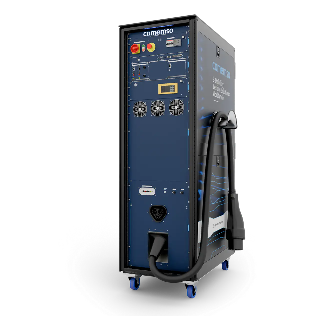
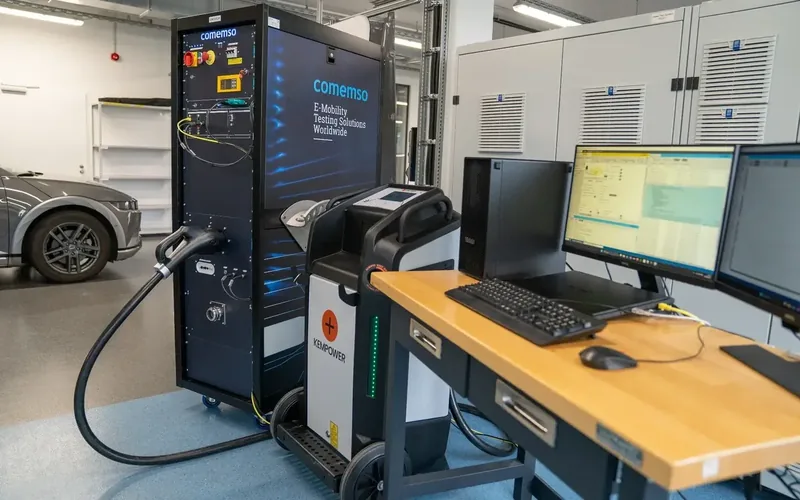
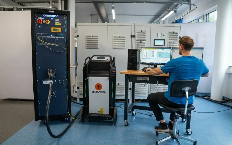
EVCA MCS simulates the charging station for MCS truck tests or the vehicle for MCS charger tests, with power and cooling for the operating points you need before the first truck charges – instead of a test setup built from scratch for each project.1
Operating points up to 1,500 A and 2.25 MW.
- What for
- Truck makers and megawatt-charger developers, before the first depot goes live.
- What it does
- Simulates the charging station or the truck, with power and cooling for operating points up to 1,500 A and 2.25 MW.
- Not for
- Car charging with CCS – that is EVCA Flex.
An MCS session that fails in the depot stops a truck – and its delivery schedule.
Dedicated MCS test equipment within the EVCA platform
MCS communication, low-level signals, thermal interfaces and scalable power in one test system.
A dedicated MCS coupler or inlet, 10BASE-T1S, MCS low-level states and connector temperatures combine with project-specific power and cooling. You configure, measure and analyse the test in the EVCA workflow.
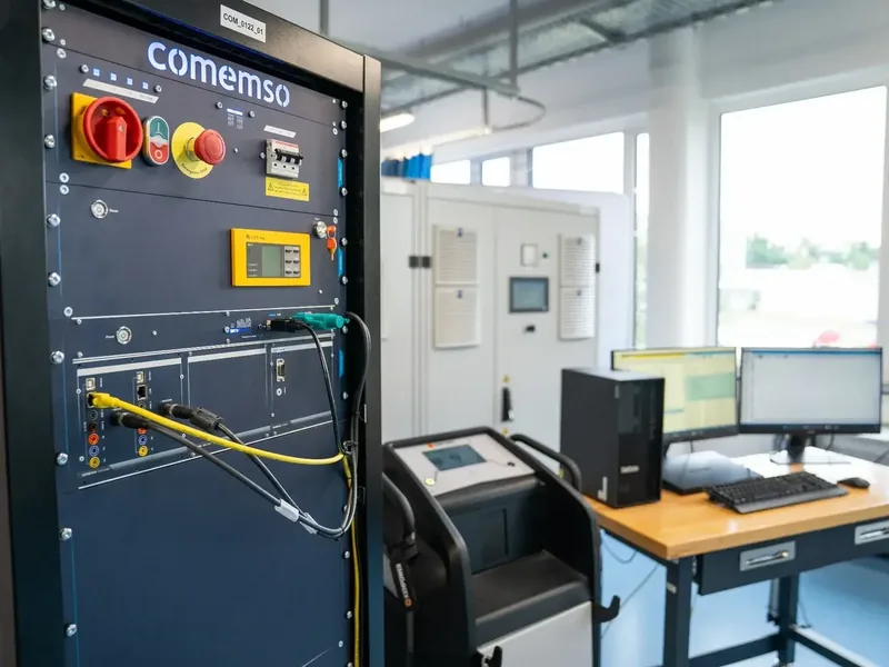
System configuration.The quotation defines the released communication edition, connector hardware, cooling, maximum and continuous duty, power equipment, measurement channels, licences, safety architecture and planned upgrade path.
Both sides of the MCS interface
System configurations for vehicles, charging stations and controllers.

Simulates the MCS charging station for EVCC (vehicle-side charging communication controller), charging subsystem and complete-vehicle tests. The MCS EVSE (charging station) simulator works with the cooled cable and external source required by the approved full-system test.
- Charging-station communication and low-level simulation
- Cooled cable and connector temperature monitoring
- External bidirectional source control
- Vehicle reaction correlated with power and timing
Simulates the heavy-duty vehicle and its battery requests for SECC (station-side charging communication controller), dispenser and full-charger development. The MCS EV simulator coordinates separately configured external DC source/load equipment for battery emulation.
- Vehicle communication and charging requests
- MCS inlet and low-level vehicle signals
- Battery-emulation and load integration
- SECC and power-stage behaviour on one timeline
Develop and test EVCC or SECC communication, certificates, 10BASE-T1S and low-level signals on the MCS controller bench.
- Communication-focused bench testing
- Individual low-level signal access
- The same test workflow, extended with full-power hardware
Communication and low-level MCS
Analyse communication, signals and power in the MCS test setup.
The released MCS configuration correlates the following layers.

The system simulates and monitors Charge Enable and Insertion Detection according to the system scope.
Shows the temperature channels that protect the high-current connection and cooling architecture.
Include the auxiliary voltage environment required by the selected MCS direction.
Measures and analyses the single-pair Ethernet environment below the application protocol.
Analyses secure communication and protocol-level BPT services. Physical reverse energy flow is a separate hardware configuration using suitable external source/load equipment; neither scope alone demonstrates complete bidirectional MCS system conformity1.
High-power testing with detailed protocol analysis
Plan the power stage for maximum and continuous operation.
We define voltage, current, maximum power and continuous operating points separately for the selected configuration. Continuous performance depends on the source or load, mains connection, cable, coupler, cooling, ambient conditions, temperature channels and duty cycle.
Published system limits
- Maximum voltage
- Up to 1,500 VPublished hardware system limit
- Maximum current
- Up to 1,500 AHigher current on request
- Maximum power
- Up to 2.25 MWPublished power class
- Continuous duty
- Project-specificPower, cable, cooling and ambient conditions
The standards-based MCS EV-side voltage range is limited to 1,250 V in the applicable scope. Device under test (DUT) ratings, released test-library configuration and continuous-duty requirements remain project-specific.
Integrated liquid cooling
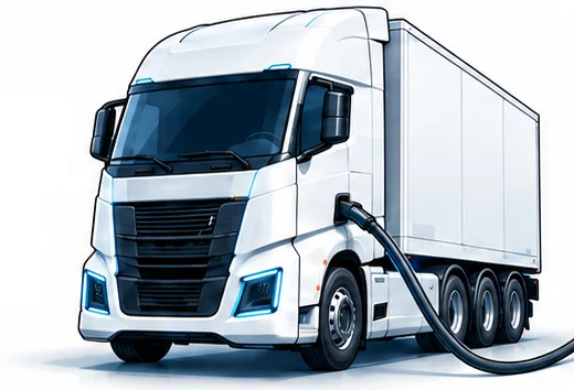
EV testing and applicable Man-in-the-Middle setups. A liquid-cooled MCS cable and rack cooling support demanding vehicle tests and applicable real-pair setups that carry high current for extended durations.
MCS inlet for charger and reduced-power tests
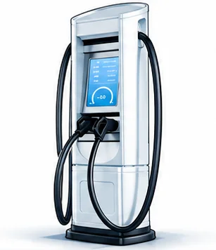
EVSE testing and reduced-power applications. MCS inlet and project-specific thermal architecture match your charger test or reduced-power application.
Product-status snapshot
Released functions and planned additions.
Current MCS datasheet status.
- RELEASED
- MCS EV and EVSE simulation, measurement and analysis
- Control of external bidirectional DC sources
- Power, signal-quality and communication measurement
- Manual control of low-level MCS signals
- Automated plugging and unplugging simulation
- Recording and comparison of complete charging cycles
- Standards-based HLC visualisation and root-cause analysis
- COMING SOON
- EV and EVSE Professional Simulation
- Gateway for encrypted communication analysis
- Manipulating Gateway for targeted changes
- Insulation-resistance monitoring
- Simulation of error cases
- Comprehensive interoperability testing
- Standards conformity and robustness testing
- REST API control of the complete test process
A function appears in the released list only after the product datasheet and software release statement have been updated.
Application Engineering confirms the current configuration, supported functions and document revision.
comframe analysis
Record, compare and evaluate complete MCS charging cycles.
Captures communication, low-level states, temperature and available electrical measurements.
Shows changes across software, vehicles, chargers and configurations.
Assess high-level communication measurements in the relevant technical context.
Released CE, ID, auxiliary and temperature conditions, set and inspected
Released bidirectional DC source or battery-emulation workflows, coordinated
Plugging and unplugging are automated for controller and charging-cycle tests where released.
Modular configurations
Expand from MCS ComOnly to full-power vehicle or charging-station tests.
Interfaces, power equipment, cooling and environmental tests join the shared MCS workflow as your programme needs them.

MCS ComOnly configuration
EVCC or SECC communication, certificate tests, 10BASE-T1S and low-level signals for controller development.
MCS EVSE simulation
Coupler, cooled cable, charging-station role, temperature channels and external source integration.
MCS EV simulation
Inlet, heavy-duty vehicle and battery requests, low-level states and external battery-emulation hardware.
Released MCS standards stack
Specify the standard edition, amendment and released functions for each layer.
IEC 61851-23-3:2026
Basis for the MCS low-level interface described in the supplied product scope, including Charge Enable and Insertion Detection.
ISO 15118-10:2025
Two-wire single-pair Ethernet physical and data-link layer based on 10BASE-T1S.
ISO 15118-20 Amendment 1
MCS charging services, secure communication, charging and discharging and bidirectional-power functions within released scope.
IEC TS 63379
Basis stated for plugs, inlets, vehicle connection and cable in the supplied product package.
Released scope.Optional services, certificate workflows and Test Libraries for the selected configuration are specified in the quotation and release matrix.
Commercial system configuration
Configure EVCA MCS for the vehicle, charger and power architecture under test.
Vehicle (EV), charging station (EVSE), EVCC, SECC or subsystem.
ISO 15118-10, 10BASE-T1S and ISO 15118-20: define the edition, services, TLS, certificates and keys.
MCS coupler or inlet, with access to CE, ID, auxiliary signals and temperature channels.
External bidirectional DC source/load, mains connection, cable, cooling circuit and flow, interlocks and environment are defined per project.
comframe functions, automation, measurements and reports follow the current system configuration. We plan the upgrade path alongside the test requirements.
Related pages and resources
Find application methods, system configurations and current release information.
Understand the complete EV, EVSE and interoperability test methods.
PlatformCommunication, mobile, interoperability, high-power and MCS system paths side by side.
SoftwareConfiguration, measurement, analysis, automation and reports.
KnowledgeTechnical layers, editions and adjacent standards pages.
Frequently asked questions
EVCA MCS product FAQ
What is EVCA MCS?
EVCA MCS is the dedicated Megawatt Charging System test path within the EVCA platform. It combines MCS communication, low-level signals, coupler or inlet, temperatures, control of separately configured external DC source/load equipment, cooling options and comframe analysis for vehicle, charging-station and controller development.
Can the platform test both MCS vehicles and charging stations?
Yes. Simulate the charging station to test the vehicle, or simulate the heavy-duty vehicle and battery to test the charger.
What are the published maximum system classes?
The hardware platform can be configured up to 1,500 V, up to 1,500 A and up to 2.25 MW, with higher current available on request. The standards-based MCS EV-side voltage range is limited to 1,250 V in the applicable scope. These maxima are independent configuration limits and must not be assumed to be simultaneously available; DUT rating, released test-library configuration and continuous-duty requirements remain project-specific.
Does the system include liquid cooling?
The dedicated rack can be configured with integrated liquid cooling for vehicle testing and applicable high-current setups. Charger and reduced-power configurations can use the inlet and a project-specific thermal architecture without the integrated rack cooling unit.
Which low-level MCS signals are supported?
The current product scope describes simulation and monitoring of Charge Enable and Insertion Detection, plug and inlet temperatures and auxiliary voltage for EV and EVSE.
What is MCS ComOnly?
MCS ComOnly is the communication-focused configuration for EVCC and SECC development without voltage and current. It provides the MCS communication and low-level environment before a full-power laboratory is required.
Customer projects, success stories and technical articles related to this page.
- KnowledgeMCS testing: communication and signalsPlan MCS communication and signal tests by interface, EV/EVSE role and edition. Identify the equipment needed for power tests.
- Product newsEV and EVSE testing with MCS expansionHistorical MCS-ready test architecture for EV and EVSE testing: charging interfaces, cooling, communication and high-power integration.
- Product newsCharIN MCS Testival Europe: Megawatt ChargingCharIN MCS Controller Testival Europe, Barcelona, 1–2 April 2025: comemso supported early EV/EVSE communication tests as an official sponsor.
MCS test planning
EV, EVSE or ComOnly system path Communication, thermal interfaces, power equipment and cooling are defined together for the required operating points.
The right EVCA path
Choose EVCA MCS to test the MCS architecture of your vehicle, charging station or controller.
| Selection criterion | EVCA ComOnly | EVCA Flex | EVCA MCS | EVCA Interop |
|---|---|---|---|---|
| Primary purpose | Controller communication without full power | AC, CCS, NACS, CHAdeMO and GB/T high-power laboratory testing | Dedicated MCS test system | Real EV and real EVSE root-cause analysis |
| Communication | Configured CCS/NACS and protocol families | Configured global charging protocols | MCS 10BASE-T1S and service stack | Protocol depends on the real pair and gateway configuration |
| Physical interface | Communication-focused | AC and DC charging interfaces | MCS coupler, inlet, CE, ID and temperature access | Real charging interface between both partners |
| Power and cooling | No full-power path | Project-specific source, load and high-power integration | Dedicated MCS power and cooling architecture | Depends on the real pair and product configuration |
| Best fit | EVCC or SECC development | Global charging development and fault testing | MCS vehicles, chargers, controllers and laboratories | Field and real-pair interoperability investigations |