
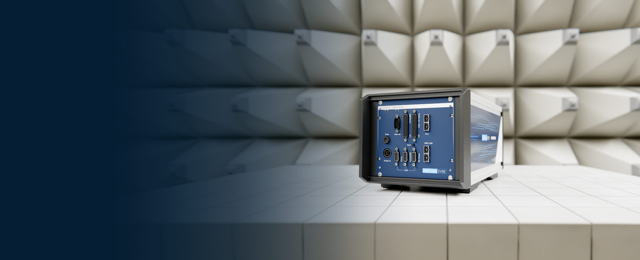
Optical charging interface for EMC testing
EMC tests during an active charging session – partner outside the chamber.
During the active charging session, EMC Link carries the charging signals over optical fibre between the device in the EMC chamber and its simulated charging partner outside – instead of copper signal lines through the chamber wall.1
Built for EMC test setups to IEC 61851-21-1, IEC 61851-21-2 and UN Regulation No. 10.
- What for
- EMC laboratories and test teams who must keep a charging session running inside the chamber.
- What it does
- Carries the charging signals over optical fibre to the simulated partner outside; the chamber-side unit runs on a filtered 12 V DC supply.
- Not for
- Protocol tests without an EMC chamber – that is EVCA ComOnly.
- Optical charging communication
- Real or simulated charging partners
- Test equipment outside the chamber
Charging faults that only appear under EMC stress stay invisible unless the session keeps running in the closed chamber.
Architecture and test setups
Device under test in the chamber, simulation and analysis outside
Chamber-side and external units match the device under test (DUT) and its charging counterpart.


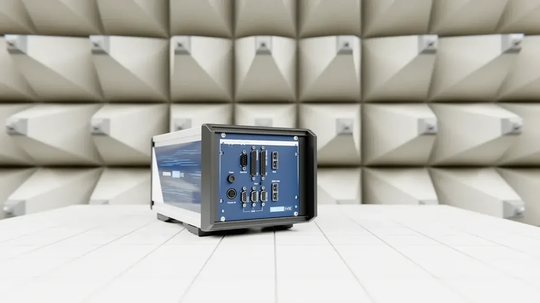
The DUT and compact EMC Link unit, with a filtered 12 V DC supply for the chamber-side unit.
Two optical fibre cables connect the chamber-side and external units.
The external unit connects to the simulated charging counterpart. A compatible EVCA/comframe configuration handles simulation, operation and analysis.
Configured signal paths
Select signal paths for your charging interface.
We configure the signal paths for the charging technology and modules in your test setup.
PLC communication
High-level powerline communication for applicable charging technologies.
Low-level charging signals
CP/PP, CS1/CS2, CC1/CC2, CE/ID and temperature, according to the selected configuration.
Auxiliary handling
A relay contact for digital control of the opposite-side 12 V auxiliary environment, where configured.
CAN and Ethernet
Supporting data paths for the selected test architecture.
How the components work together in the test setup
- Optical signal transport
- EMC Link and the selected modules carry the released signal paths transparently.
- Simulation and analysis
- The connected test system handles simulation, protocol decoding, manipulation, logging and automation. A compatible EVCA/comframe configuration provides these functions when included in the setup.
- Charging power and safety
- External sources, loads and laboratory infrastructure provide power conversion, charging power, cooling and safety functions. EMC Link does not transfer charging power.
- EMC measurement and assessment
- The laboratory provides the stimulus, instruments, limits and assessment according to the agreed test plan. EMC Link does not produce an EMC compliance verdict.
Technology-specific modules
Choose the charging technology and matching modules.
Software-controlled selection works within the supported scope.
AC
Control Pilot and proximity paths for charging-state behaviour.
CCS
Combo 1 and Combo 2, with the configured low-level paths and PLC communication.
NACS
Configured charging signal paths and PLC communication.
CHAdeMO
Technology-specific low-level signals and CAN communication.
GB/T DC
CC1/CC2, CAN and the configured interface signals.
Standards and test scope
Define the applicable EMC test requirements.
Standard and operating conditions follow the device under test.
Vehicle and onboard charger
EMC requirements for vehicle-side charging units, tested in the complete vehicle or as an electronic subassembly within the applicable scope.
Off-board charging equipment
EMC requirements for external EV charging systems and their applicable operating modes.
Vehicle approval context
The approval plan specifies regulatory series, annex, active charging state and required laboratory geometry.
Harmonics and flicker
Dedicated grid and measurement equipment evaluates AC mains behaviour. EMC Link maintains the configured communication path.
Planning documents and a practical test setup
Coordinate signal paths, test equipment and the laboratory workflow.
Selection and installation
Configure EMC Link for your test setup.
When do I need EVCA?
Use a compatible EVCA/comframe configuration to simulate the charging partner, analyse protocols, record results or automate control as required by the test. EMC Link connects the signal paths optically; the connected test system performs simulation and analysis.
What is required for chamber installation?
Plan two optical fibre cables, suitable feedthroughs and a filtered 12 V DC supply for the chamber-side unit. The laboratory defines the cable routing, filtering, external power and safety integration for the approved setup.
Are all charging technologies included in a base configuration?
MCS follows a separate product and configuration path.
Customer projects, success stories and technical articles related to this page.
- Success storyTÜV Austria: certification and EMC testingWatch the comemso customer reference from TÜV Austria, presented in the EV Charging Analyzer portfolio under certification and EMC testing.
Configure your test setup
Define your EMC Link configuration with these five test-setup details.
- DUT, standard and operating condition
Describe the vehicle, OBC, inlet, controller, EVSE or module under test. Specify the applicable standard edition and test mode.
- Charging counterpart
Choose EVSE simulation for a vehicle-side DUT or EV simulation for a charging-station-side DUT.
- Technology and signal scope
Specify the connector family and the required PLC, low-level signals, CAN, Ethernet, temperature and auxiliary paths.
- Chamber integration
EMC or climate chamber, fibre routing, feedthroughs, filtered 12 V supply, artificial network/AAN, harness geometry, external power and safety.
- Results and software
Specify compatible test-system functions for logging, analysis, control and reporting, including EVCA/comframe where configured.
15-minute demo. An engineer shows a charging session over EMC Link – DUT in the chamber, simulated partner outside.Written quotation. The five setup details above, in one quotation – then you order.Delivery and start. Commissioning and training are agreed in the quotation.