
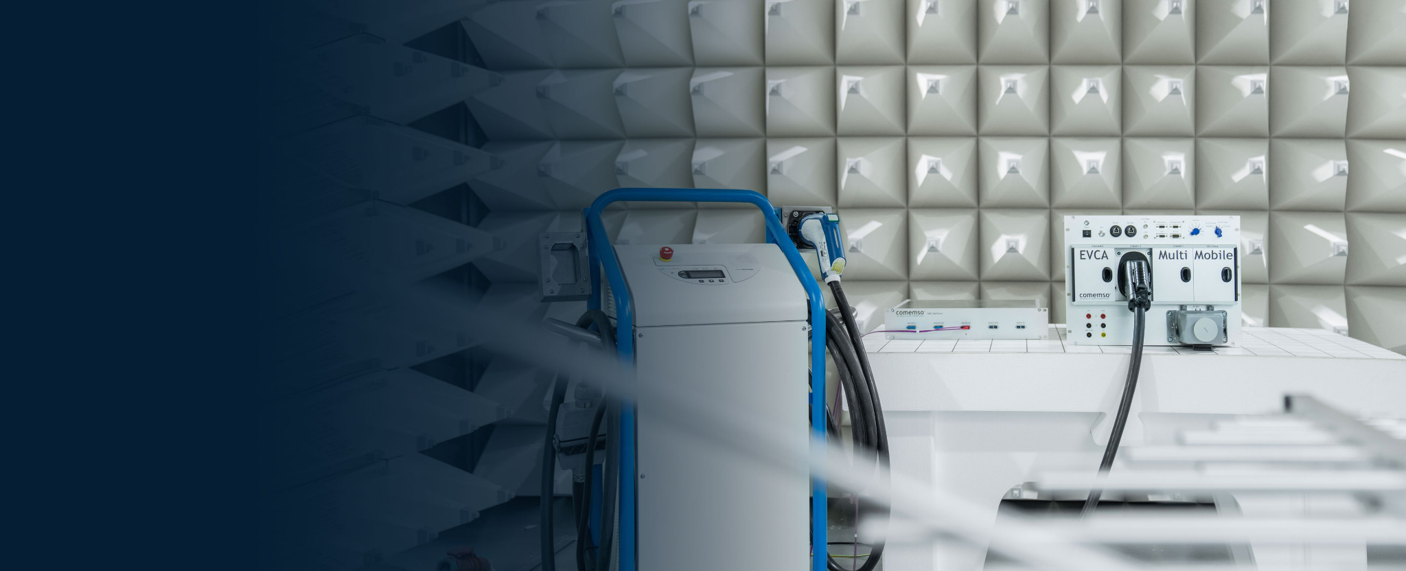
EV and EVSE EMC testing
See how charging reacts to EMC stress, during the test.
EMC Link keeps the charging session running while the vehicle or charger sits in the EMC chamber, and EVCA records communication alongside the test condition – instead of judging the device only before and after exposure.1
For EMC test setups to IEC 61851-21-1, IEC 61851-21-2 and UN Regulation No. 10.
- What for
- EMC laboratories and vehicle or charger teams who must see how charging reacts during exposure.
- What it does
- EMC Link keeps the session running in the chamber over optical fibre, chamber-side on a filtered 12 V supply; EVCA records communication alongside.
- Not for
- Functional charging tests without EMC exposure – that is EV testing or EVSE testing.
A charging fault that only appears under EMC stress passes the test unnoticed – and shows up at the customer.
The EMC condition, linked to the charging response
Identify what changed when the EMC condition was applied.
Charging depends on communication, pilot state and the power path working together. Compared with the device under test (DUT) response, they show whether the setup remained valid when the EMC condition was applied. A protocol trace alone cannot establish this.
First you define DUT and acceptance criteria. Then use the agreed test requirements to choose the charging counterpart, required operating state, chamber boundary and recording channels.
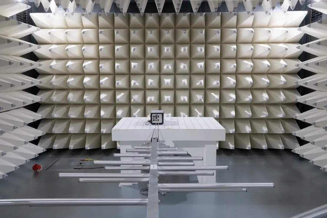
The vehicle or the charging station is the device under test
Use the same measurement method for EV and EVSE tests.

EV, OBC or EVCC under stress
Place the complete vehicle, charging inlet, onboard charger or vehicle-side controller in the EMC environment. EVSE (charging station) simulation, control and analysis stay outside.
- The vehicle-side DUT and applicable ports
- EVSE simulation remains operational outside the chamber
- Pilot states and protocol messages, related to the vehicle response
EVSE, module or SECC under stress
Place the charging station, charging module or supply-equipment controller in the chamber. EV simulator, control and analysis stay outside.
- The EVSE-side DUT and operating mode
- EV simulation remains operational outside the chamber
- Communication and charging state, related to the station response
Define the test scope from the applicable standard.
Document and edition come first
Vehicle tests, off-board charging-equipment tests, regulatory approval and AC power-quality tests have different scopes and laboratory responsibilities. You specify exact document, edition, DUT operating mode and project acceptance criteria before configuring the setup.

Applies to the onboard charging unit, either in the complete EV or as an electronic subassembly, while conductively connected to the supply.
Covers off-board conductive charging equipment and defines ports, operating modes, test setups and limits for the EVSE-side route.
The applicable series of amendments, revision and approval route apply. The short name “ECE R10” is not a complete project definition.
These are separate power-quality routes where applicable. Grid sources, analyzers, impedances and the final assessment remain dedicated laboratory functions.
EMC Link carries the selected charging-specific signal path across the chamber boundary. The laboratory provides antennas, disturbance generators, artificial networks, power analyzers, chamber procedures and the final verdict.
Keep the charging configuration for the EMC sequence
Reach the charging state, then run the EMC sequence.

- 1Define
Define DUT, standard, ports, condition, counterpart and acceptance criteria.
- 2Configure
Set the charging technology, simulation parameters, signals and recording channels.
- 3Establish
Connect, negotiate charging and reach the required phase.
- 4Apply
Execute the approved conducted or radiated laboratory sequence.
- 5Capture
Record the EMC condition alongside charging state, messages and DUT response.
- 6Repeat
Repeat the same configuration to check corrections and run regression tests.
The published EMC Link concept is designed for stable charging interaction during long immunity and emissions sequences. Reducing interruptions avoids repeated restarts and makes the runs easier to compare.
Connect the signals required by the charging technology.
Charging communication and signals
We configure the optical path for the active charging session. It carries the selected charging signals; general network bridging and charging power are outside its scope.
PLC (power line communication) for the applicable charging technologies.
Control Pilot (CP)/Proximity Pilot (PP), CS1/CS2, CC1/CC2, CE/ID and temperature paths as configured.
Digital relay control for the published 12 V AUX handling concept.
Use CAN and Ethernet as supported by the released laboratory configuration.
High-level communication
PLC charging communication through the optical path.
Low-level charging signals
CP / PP, CS1 / CS2, CC1 / CC2, CE / ID and temperature.
Auxiliary control
Vehicle and test interfaces
Analysis outside the chamber
EVCA and comframe logging, analysis, simulation and reports.
Published charging technologies
- AC
- DC-CCS Combo 1
- DC-CCS Combo 2
- NACS
- CHAdeMO
- GB/T DC
- MCS. Separate route
Provide charging power, sources, loads, chamber feedthroughs, cooling, interlocks and electrical safety through the external laboratory setup.
EMC condition and charging data, compared
Locate the first relevant change on the timeline.
Shows the timing of the EMC condition, first deviation and DUT recovery. This sequence separates an electromagnetic effect from a protocol, setup or system issue.

What was applied?
Test step, level, frequency range, dwell or laboratory event.
What changed in charging?
Messages, timing, pilot state, measurements and charging phase.
How did the device under test respond?
Continued operation, transition, derating, interruption, stop or recovery.
Can the run be repeated?
Configuration, trace and technical assessment stay together for a repeatable rerun.
Connect the device under test inside to the simulated counterpart outside.
Optical link and external test system
The setup for the chamber method. We confirm interfaces, connectors, software functions and licences released for the project configuration.
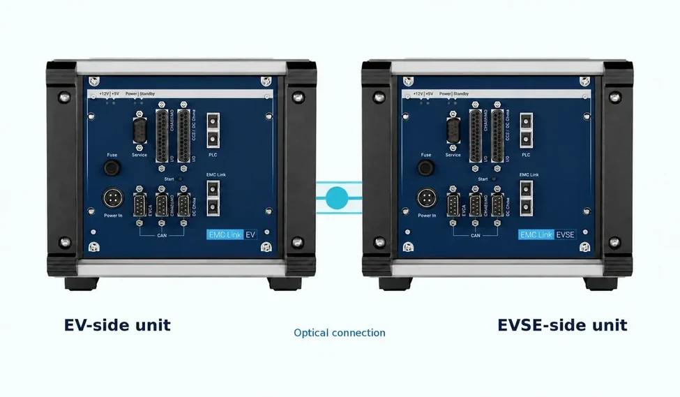
Transparent signal path
EMC Link carries the configured charging signals between the DUT in the chamber and EV or EVSE simulation outside. The connected test system generates the simulated charging counterpart.
EV in the chamber
EVSE simulation, control, measurement and analysis stay outside while the vehicle side is exposed.
EVSE in the chamber
EV simulation, control and analysis stay outside while the charging-station side is exposed.
EMC or climate environment
An isolated optical path keeps the DUT connected to its charging counterpart in the EMC or climate environment.
Roles in the test setup
Assign signal transport, test control and the laboratory tasks.
- Optical charging-specific signal transport
- Signal transport separate from charging power
- Supported charging communication and low-level signal paths
- Chamber-side and external-side units
- EV or EVSE simulation
- Logging and synchronised analysis
- Debugging and simulation control
- Automation and reporting where configured
- Generate and measure the EMC condition
- Antennas, networks and chamber setup
- Power, loads, cooling and safety
- Acceptance criteria and final verdict
Configure the setup for the chamber test.
The agreed test scope
The optical link for the actual test
Vehicle, inlet, controller or charging station
EVSE simulation for an EV DUT; EV simulation for an EVSE DUT
AC, CCS / NACS, CHAdeMO, GB/T DC or separate MCS path
PLC, low-level charging signals, CAN, Ethernet and AUX
EMC or climate chamber, supply filtering and fibre routing
External test-system functions handle logging, analysis and reports.
EMC Link configuration + compatible EVCA path + approved chamber setup
Equipment and references for the EMC setup
Choose the equipment for each test task.
Optical hardware, topologies, signal paths and configuration inputs.
PlatformEV and EVSE simulation, measurement, analysis and laboratory automation.
StandardsYou check document, edition, DUT role and scope before testing.
Official brochurePublished technology coverage, signal transport, architecture and setup notes.
Contact support about an existing configuration or a reproducible issue.
Frequently asked questions
EV charging EMC test FAQ
Build the final test plan from the exact project standard, released product documentation and approved laboratory procedure.
What is EV charging EMC testing?
EV charging EMC testing checks the response of an EV, onboard charger, EVCC (vehicle-side charging communication controller), EVSE or SECC (station-side charging communication controller) under a defined electromagnetic condition. Record the charging state, DUT response and applied or measured laboratory condition together so their relationship can be checked.
What is the difference between EV EMC testing and EVSE EMC testing?
EV EMC testing places the vehicle, inlet, onboard charger or EVCC in the chamber while EVSE simulation remains outside. EVSE EMC testing places the charging station, module or SECC under stress while EV simulation remains outside.
Why use an optical link at the chamber boundary?
The optical path carries the selected charging communication and low-level signals across the chamber boundary without extending a conventional copper communication path. Plan fibre routing, filtered supply, charging power and chamber feedthroughs as part of the approved laboratory setup.
Can EMC Link operate without an EVCA test system?
Combine EMC Link with a compatible test system that provides the simulated EV or EVSE counterpart, control and analysis. EVCA and comframe provide these test functions when included in the agreed configuration. Confirm the interfaces and software scope if another external system is selected.
Customer projects, success stories and technical articles related to this page.
- Success storyTÜV Austria: certification and EMC testingWatch the comemso customer reference from TÜV Austria, presented in the EV Charging Analyzer portfolio under certification and EMC testing.
The charging test for the chamber
We specify DUT, disturbance programme, active charging states and pass/fail criteria per project. Chamber instrumentation, optical signal transport and charging simulation each have their role in the setup.
15-minute demo. An engineer shows the charging states for your chamber test on a real EVCA system.Written quotation. Everything we specify together, in one quotation – then you order.Delivery and start. Commissioning and training are agreed in the quotation.