
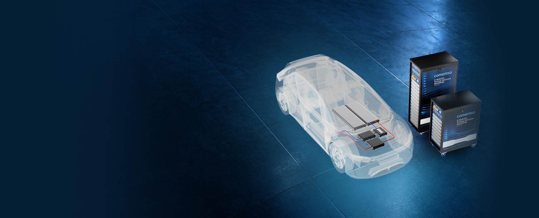
EVCC, BMS and OBC integration testing
Test EVCC, BMS and OBC together – before the vehicle exists.
EVCA simulates the charging station, the Battery Cell Simulator replaces the battery, and both record messages and measurements on one timeline – instead of waiting for a complete vehicle to find integration faults.1
12 to 300 simulated cells plus a simulated charging station in one integration setup.
- What for
- Vehicle teams who must test EVCC, BMS and OBC together before a complete vehicle exists.
- What it does
- EVCA simulates the charging station; the Battery Cell Simulator replaces the battery with 12 to 300 cells; everything lands on one timeline.
- Not for
- Testing a BMS on its own – that is BMS testing.
An integration fault found in the prototype vehicle costs weeks; found in the field, it costs a recall.
Test scenario: Follow one condition through the controllers
Illustrative test: the BMS detects a temperature that requires a lower charging current. The EVCC must communicate the changed limit. During AC charging, the OBC must adjust its operation accordingly; during DC charging, the external charger supplies the battery-side power. Limit message and measured current share the same timeline.
Battery safety during charging
A critical cell must end the charging session.
About one in six EV fires starts while the vehicle is charging. In South Korea, 17.2 % of 238 recorded EV fires between 2016 and 2024 occurred during charging; a global collection of verified battery fires reports around 15 % during charging or within one hour afterwards.2
If a cell overheats or is overcharged, the BMS usually detects it. That alone does not make the vehicle safe: the information must reach the vehicle controller (VCU) and the EVCC so that the charging current stops – via the OBC in AC charging, via the charging station in DC charging. Only then can the BMS take countermeasures such as cooling without further stressing the cells or provoking thermal runaway.
The statistics do not show why each fire started. They show why the shutdown chain during charging deserves its own test: every link can fail.

The BMS misses the overvoltage or overtemperature. The Battery Cell Simulator sets the critical value on one cell precisely and repeatably.
The stop request reaches VCU, EVCC or OBC too late, inconsistently or not at all. Where the configuration supports it, the test delays or suppresses messages.
OBC or charging station keep supplying power. The test records on one timeline how fast the charging current reaches zero in AC and DC charging.
After the stop, charging must not resume while the cell is still critical. The test checks stop reason, contactors and restart behaviour.
Pass criterion: charging current at zero within the response time defined in your safety concept, contactors in the defined state, no restart while the condition persists.
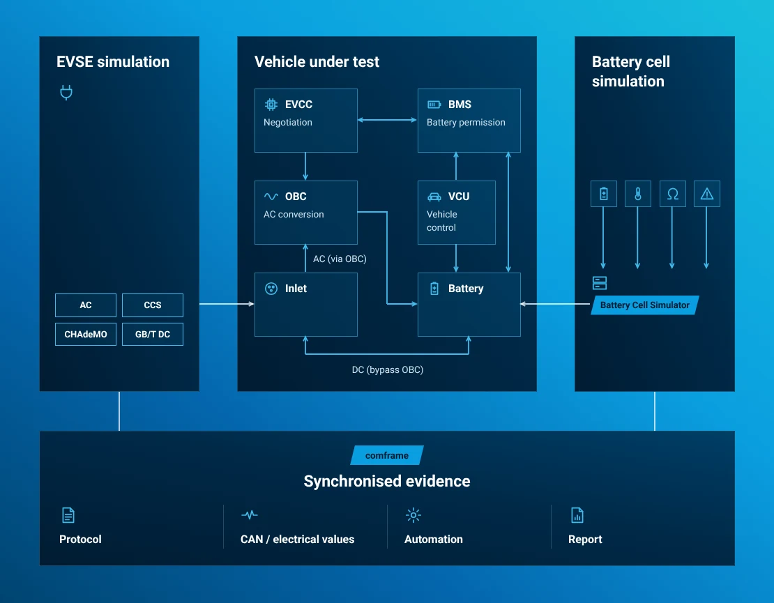
Follow the charging decision through EVCC, BMS and OBC.
You set battery state and charging counterpart on an ECU bench, in a vehicle subsystem or in the complete EV.
The AC path includes the OBC; direct DC CCS, CHAdeMO and GB/T DC charging bypasses it. Cell-level BMS validation and pack-level power remain distinct parts of the configured test environment.
A shared vehicle state
Check each charging request against the current battery limits.
A formally valid EVCC request may conflict with a BMS power reduction, isolation fault or stop request. The combined response matters: controllers that pass separate bench tests may still make inconsistent decisions together.
One electric-vehicle decision chain
The test checks the message against the vehicle state.
All controllers must act on the same vehicle state.
- EVCA
Represents the EVSE
- Charging protocol
- Low-level states
- Power and fault context
- Controlled counterpart
- EVCC
Negotiates charging
- Voltage and current request
- Service and protocol state
- Certificates and timing
- Stop and error messages
- BMS
Permits battery use
- SOC and power limits
- Temperature and isolation
- Contactor permission
- Fault and recovery state
- Vehicle controls
Coordinates the action
- VCU and thermal control
- Pre-charge and contactors
- OBC enable and derating
- Safe-state coordination
- Physical response
Executes the decision
- OBC or direct DC path
- Voltage and current
- Safe stop and recovery
- Synchronised recordings in comframe
- EVCC messages
- BMS and vehicle CAN
- OBC and contactors
- Voltage and current
- Expected relation
Limit mismatch
The EVCC requests more voltage, current or power than the BMS currently permits.
State mismatch
Charging readiness, contactors, isolation and protocol state no longer describe the same vehicle condition.
A delayed response
A battery or thermal event reaches the charging communication or power interface too late.
You trace why charging stopped
A session can stop correctly at the final layer while the cross-system deviation that triggered it remains unclear.
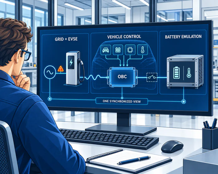
Integrated AC charging and EV OBC testing
Test the onboard charger with its enable, limit and stop commands.
An EV OBC test brings the AC charging interface and OBC conversion together with EVCC, BMS, VCU, contactor logic, thermal limits and battery-side conditions.
Before enabling the OBC, compare the EVCC request with BMS voltage, current, SOC, temperature and safety limits.
Within the configured test scope, check enable, power factor, efficiency, derating, diagnostics, current response and controlled shutdown.
One vehicle sequence follows pre-charge, high-voltage enable, thermal derating, fault propagation and recovery.
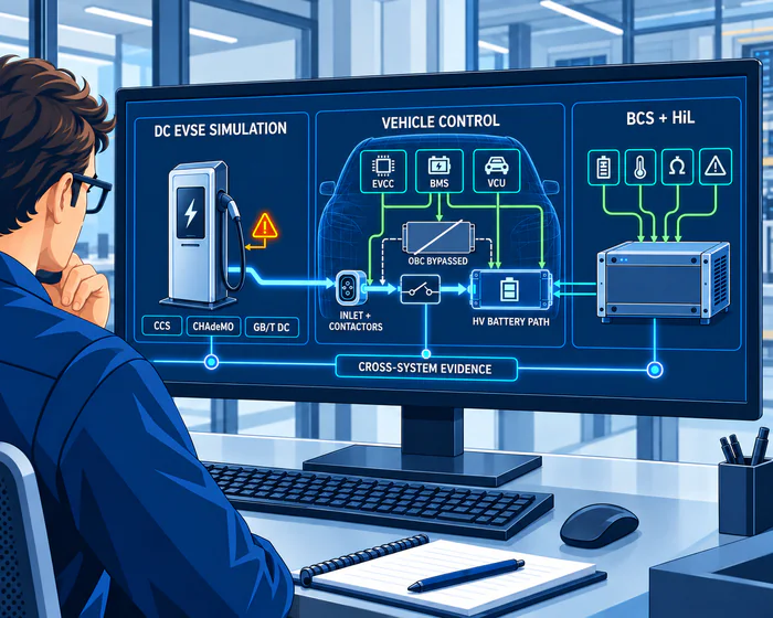
Direct DC charging integration
Coordinate DC CCS, CHAdeMO and GB/T DC charging with the OBC bypassed.
In direct DC charging, the station supplies the HV battery path through the inlet and contactors. Shows whether EVCC, BMS, VCU, isolation monitoring, thermal control and the switching sequence agree on the permitted operating point and respond correctly to changed limits or faults.
PLC charging communication
DIN 70121 or ISO 15118 communication lines up with Control Pilot (CP) and Proximity Pilot (PP) state, requested limits, contactors, isolation, voltage and current.
CAN-based charging communication
CHAdeMO messages and timing are compared with battery permission, charging state, physical output and the safe-stop response.
GB/T 27930 and vehicle state
The test compares GB/T communication, interface conditions, BMS limits and the contactor sequence with the measured DC response.
EVCA, Battery Cell Simulator, comframe and external power equipment follow the required protocols, editions, low-level interfaces, power ranges and fault functions.
Charging limits and fault responses, tested
Follow a changed battery limit through to the charging response.
Change one controlled condition per run. Record the charging request, battery state, controller reactions and physical result. Check the resulting state and timing against the pass criterion.
Checks wake-up, readiness, pre-charge, contactors, negotiated limits and the start of energy transfer.
Change the voltage, current or power permitted by the BMS. Measures how quickly the EVCC and physical power path follow.
Cell, pack, OBC or cooling limits show whether derating is coordinated and control stays stable.
Verifies detection, communication, switching sequence, safe state and recovery after a defined safety condition.
Compares converter diagnostics and available power with the states reported by BMS, EVCC and VCU.
Compares protocol readiness and physical switching with the measured high-voltage response.
Where the configuration supports it, the test injects delayed, missing or inconsistent vehicle-network and charging information.
Checks the stop reason, message sequence, current ramp, contactor opening, remaining states and restart behaviour.
Overvoltage or overtemperature on one simulated cell during AC or DC charging. Checks detection, stop request, current ramp to zero, contactors and restart lock.
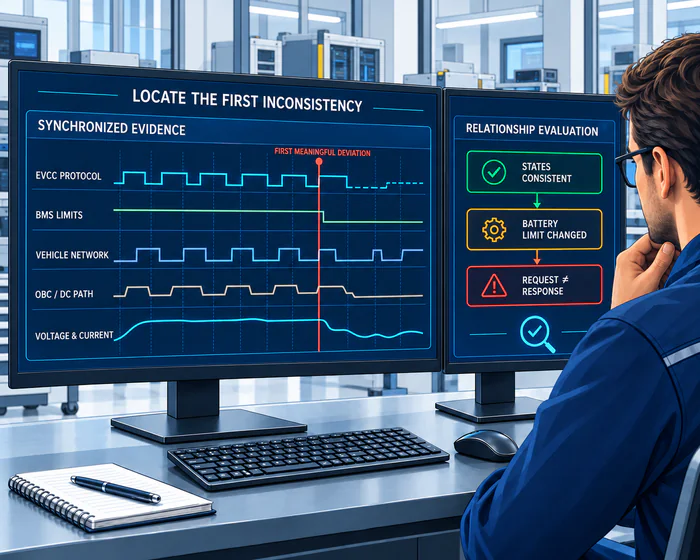
The systems on one timeline
Trace the charging error back to the first inconsistency.
With comframe, the engineer can compare charging communication, vehicle-network states, BMS limits, OBC or direct-DC behaviour and electrical measurements on a shared time base. Shows whether each system reacted to the same condition within the required time.
Integration test matrix
Each changed condition has its expected response.
| System or signal | Nominal relation | Changed condition | Expected consequence | Required results |
|---|---|---|---|---|
| EVCC request | Request remains inside current BMS permission | Voltage or current demand exceeds a new limit | Request is reduced or charging stops within the defined timing | Message, timestamp, active limit and physical response |
| BMS permission | SOC, temperature, isolation and cell states permit charging | Thermal, cell or safety boundary is reached | Permitted power changes and the responsible controllers react coherently | BMS state, CAN signal, diagnostic reason and release condition |
| OBC or direct DC path | Power conversion or direct battery path follows the permitted operating point | Converter derating, DC limit or power-stage fault | Actual voltage and current remain consistent with the communicated state | Command, converter or power-path state, measured voltage and current |
| Contactors and pre-charge | Switching state matches charging readiness and high-voltage conditions | Pre-charge timeout, contactor mismatch or unexpected opening | Energy transfer is inhibited or stopped without an invalid intermediate state | Contactor command, feedback, HV bus and protocol transition |
| Isolation and HVIL | Safety conditions permit the selected charging phase | Isolation or interlock state becomes invalid | Fault is propagated and the system reaches the defined safe state | Measured condition, diagnostic path, stop reason and recovery sequence |
| Vehicle network | EVCC, BMS, VCU, OBC and thermal controller share consistent information | Message loss, latency or conflicting state | Timeout, fallback or safe stop follows the approved strategy | CAN or Ethernet timing, controller state and resulting charging behaviour |
EVCA + Battery Cell Simulator + comframe
Bring EVCA, Battery Cell Simulator and comframe into the vehicle test.
EVCA provides the charging counterpart, the Battery Cell Simulator supplies BMS inputs, and comframe connects configuration, synchronised measurement, automation and results. The customer provides the real vehicle controllers and the authoritative vehicle safety concept.
System components and integration details
Charging-station counterpart
EVSE (electric vehicle supply equipment, or charging station) simulation, communication, low-level states, charging measurements, configurable behaviour and applicable faults.
Explore the EVCA platformControlled battery state
Virtual cells, temperature sensors, balancing, isolation, current-related conditions and electrical fault states.
Explore the BMS testerConfiguration, measurements and results
Time-correlated charging and vehicle data, automated sequences, expected relationships, results and integration interfaces.
Explore comframeProject-specific energy path
Grid and battery emulation, sources, sinks, power measurement, cooling and safety follow the AC or DC test objective.
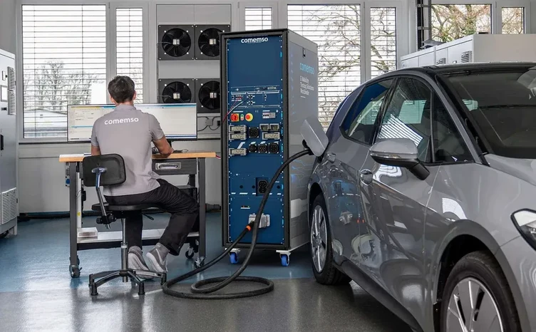

The joint comemso and Cinergia architecture shows one way to integrate grid and battery emulation with EVCA. We select external power equipment for the project; other suppliers work too.
Prepare the test, run it and keep the results.
Identify real and simulated controllers, vehicle networks and the power path. Set the battery state, charging counterpart and nominal, boundary or fault condition within the approved power, cooling and safety setup.
During the test, compare charging messages, BMS and vehicle-network states, OBC or direct-DC behaviour, contactors and electrical measurements on one timeline. Keep device under test (DUT) versions, configuration, deviations and results for regression.
Choose the next vehicle or BMS test.
Explore EV Testing for vehicle lifecycle testing, BMS Testing for cell-level validation, or the EVCA and Battery Cell Simulator product pages to choose the system.
Supported Standards and the released Test Libraries define the relevant verification scope.
Coordinate the test across the vehicle teams.
Vehicle OEMs coordinate charging release across controllers. EVCC and BMS suppliers check their interface responsibilities. OBC teams compare converter diagnostics and derating with the permitted battery limits. Laboratories can repeat the same scenarios across hardware and software variants.
Frequently asked questions
EVCC, BMS and OBC: frequently asked questions
Why is charging critical for battery safety?
About one in six EV fires starts during charging: in South Korea, 17.2 % of 238 EV fires between 2016 and 2024. During charging, current keeps flowing into cells that may already be overheated or overcharged. The BMS must detect this, and the stop must reach the OBC or the charging station through the vehicle controller and EVCC. The integration test checks this complete chain, not only the detection.
Why should EVCC and BMS be tested together?
The EVCC negotiates charging; the BMS sets battery limits and safety-related permission. Compare requested voltage and current with SOC, temperature, isolation, contactors and faults. Integration testing checks that the vehicle reaches the correct combined state, which separate ECU tests alone cannot establish.
Why is the OBC part of this integration test?
During AC charging, the onboard charger converts grid-side AC power into DC power for the HV battery. EVCC, BMS, VCU, thermal control and contactor states command or limit its enable, current demand, derating, diagnostics and stop behaviour. Check these interactions in addition to testing the OBC itself to establish the complete EV charging response.
What changes during direct DC charging?
For DC CCS, CHAdeMO and GB/T DC, the external charging station supplies the high-voltage battery path through the inlet and contactors. The OBC is bypassed in the energy path, but EVCC, BMS, VCU, isolation monitoring, contactors and thermal control still coordinate the request, permission and safe physical response.
Can the integration be tested before a complete vehicle exists?
Yes. EVCA can provide the simulated charging-station counterpart and the Battery Cell Simulator supplies controlled cell, sensor, balancing, isolation and fault conditions to the BMS. Combine them with customer vehicle networks, controllers and HiL components on a subsystem bench before the complete vehicle or traction battery is available.
Which charging technologies are relevant to EVCC–BMS integration testing?
The current application scope covers AC charging with the OBC and direct DC vehicle charging for DC CCS, CHAdeMO and DC China / GB/T DC. Exact standards, versions, connector hardware and available functions depend on the selected system release and configuration.
Which variables should be correlated?
Typical variables include requested and permitted voltage and current, SOC, cell and pack temperatures, isolation, contactor and pre-charge states, OBC commands and diagnostics, charging readiness, protocol messages, vehicle-network data, physical voltage and current, stop reasons and recovery timing.
Vehicle-side test planning
The test follows a changed battery limit from the charging request to the electrical response. We define AC and direct-DC scenarios, controller interfaces and expected response times before configuring the combined setup.