
Analyse charging behaviour against standard requirements
Automated Standards Analysis checks recorded charging communication and timing against the configured DIN 70121 and ISO 15118 requirements. Analyse the highlighted deviations: the view brings the measurements and expectations together for engineering review.
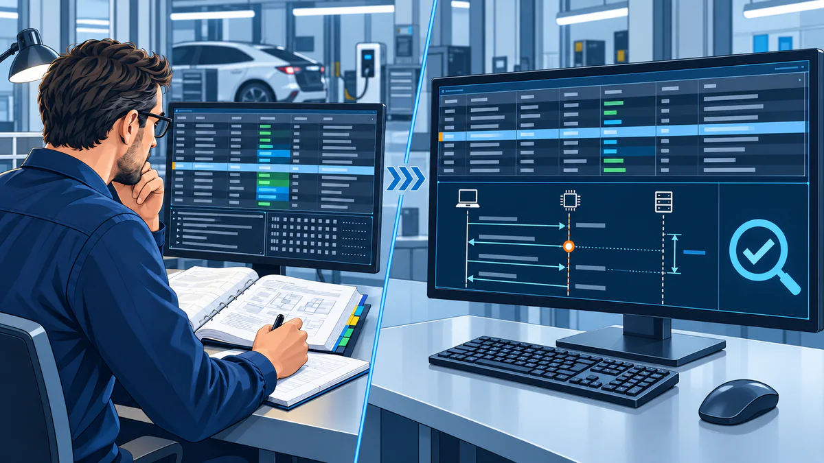
Test scenario: a response arrives after the expected window
Illustrative timing example, not a quoted standard limit: a test expects a response within 100 ms, but the recording shows 120 ms. The useful result connects the measured event, the 100 ms expectation and the 20 ms deviation. In a real test, the selected standard, message and charging phase define the applicable expectation.
| Event | Expected | Measured | Deviation |
|---|---|---|---|
| Partner response | Within 100 ms | 120 ms | 20 ms after the example limit |
From a highlighted deviation to the next test
The evaluated event opens on the original measurements, so the deviation can be investigated.
Measured event, expected behaviour and highlighted deviation show the cause, the next test and whether your change worked.

Automate recurring comparisons
Review the source data alongside the applicable standard requirements in a repeatable charging test workflow.

DIN 70121 and ISO 15118 timing analysis with the applicable timing window
DIN 70121 and ISO 15118 timing analysis compares measured messages and state transitions with the applicable timing window. It highlights late, early or missing events. The original trace stays available for detailed engineering review.

DIN 70121
Shows supported message timing and charging sequences for the configured implementation.
ISO 15118-2 and -3
High-level communication lines up with PLC (power line communication) and low-level timing where the selected EVCA configuration provides the required channels.
ISO 15118-20
Release-approved analysis functions evaluate supported message sequences and timing.
Review DC charging states throughout the session
The Cross-Layer State Monitoring brings the measured event and expected charging sequence together. PLC message type, Control Pilot (CP) state, Proximity Pilot (PP) state, DC voltage and DC current appear in the active charging phase.

Expected, missing or excessive
Highlight missing states, missing values and behaviour in the wrong charging phase for review.
IEC 61851-23 Annex CC with measured data
Software, power-electronics and system teams can use the sequence view to discuss the same charging event. Exact panel content and standard edition require release approval.
One method. Technology-specific charging states for DC CCS, CHAdeMO and GB/T DC.
Cross-Layer State Monitoring checks whether protocol messages, low-level signals, state transitions and electrical values form a permitted, technically consistent combination during charging. Each technology has its own communication and signal layers. The measurement and evaluation method remains the same.
PLC, CP/PP and electrical state
- DIN 70121 and ISO 15118 communication
- CP and PP state context
- IEC 61851-23 charging phases and Annex CC context
- DC voltage, current and expected transition
CAN communication and CHAdeMO state context
- CHAdeMO CAN messages and timing
- Technology-specific control and connector states
- Charging sequence and permitted combinations
- DC voltage, current and reaction of both partners
GB/T CAN communication and low-level state
- GB/T 27930 communication and timing
- GB/T 18487.1 interface and state context
- Technology-specific charging phases
- DC voltage, current and highlighted deviation
Trace a charging deviation across the configured layers
Protocol messages correlated with CP, PP, voltage and current show whether the event began in communication, low-level control or power behaviour.

A real customer investigation
The timing matched. The voltage response did not.
The EVCA precharge customer story shows how communication and electrical measurements support a joint investigation. The charging sequence alone did not explain the voltage response. How the recorded data helped the teams investigate the real EV–EVSE interaction.
Choose analysis, simulation or conformance testing for your task
Captured data shows a charging event. Continuous analysis reviews supported rules. A configured test case provides a controlled stimulus and an explicit evaluation.

Professional Simulation
The behaviour under test is configurable, including supported message content, timing and non-conform variants.
Conformance Test Libraries
Defined test cases run with verdict logic for a supported implementation profile.
Interoperability & Charging Analysis
Synchronised recordings investigates a real EV and EVSE (charging station) interaction and reproduces the issue.
Use the same analysis when you repeat the test
Charging protocol analysis serves development, recordings of real charging pairs and repeatable campaigns. The EVCA system follows the standards, measurement layers and evaluation panels you need.
Timing, states and charging behaviour are reviewed during controller integration, before the complete power environment exists, or during vehicle validation.
See how the simulated or real vehicle reacts to SECC (station-side charging communication controller) behaviour, charging states and measured power transitions.
Synchronised recordings with their evaluated context let both implementation teams discuss the first deviation.
Measured behaviour and normative expectation stay together for repeatable laboratory decisions and customer communication.
Released evaluation logic applies the same analysis to each configured test, across variants.
Share the evaluated event and original trace with software, controller, power-electronics and system partners so they can investigate the issue together.
Choose the device, standard and measurements for the test
Measurement layers, standard references, evaluation panels, outputs and EVCA system are defined alongside the protocol.
- DUT and test role
EV, EVSE, controller or real charging pair
- Charging standard
Protocol family, version and implementation profile
- Measured layers
Messages, timing, CP, PP, voltage and current
- Evaluation scope
Timing, states, values, phases and normative limits
- Evidence output
Monitoring view, traces, reports and exported data
- System path
ComOnly, Multi Mobile, Interop, Flex or MCS configuration
Selected EVCA system + released analysis coverage + approved normative references
Automated Standards Analysis FAQ
What is Automated Standards Analysis?
Automated Standards Analysis compares measured charging behaviour with applicable timing, states, phases and normative expectations. It highlights matches and deviations, bringing the results together for technical review.
How is this different from a protocol trace viewer?
A trace viewer displays messages and timestamps for manual comparison with the relevant standards. Automated Standards Analysis adds the applicable requirements, correlates configured measurement layers and highlights deviations in the charging workflow.
Does Automated Standards Analysis replace the test engineer?
No. It removes repetitive comparison work and presents the measurement, expectation and deviation together. The engineer remains responsible for technical interpretation, root-cause confirmation, product decisions and the approved test conclusion.
Which standards can be included?
The capability scope can include DIN 70121 and ISO 15118 timing analysis as well as IEC 61851-23 Cross-Layer State Monitoring for DC CCS, CHAdeMO and DC China / GB/T DC.
How is ISO 15118 timing evaluated?
DIN 70121 and ISO 15118 timing analysis compares a measured message or state transition with the applicable timing expectation. It shows the actual timestamp and configured normative window so you can review late, early or missing events.
What is the Cross-Layer State Monitoring?
The Cross-Layer State Monitoring places the measured charging session in the context of the expected DC charging sequence. Depending on configuration it combines PLC message type, CP and PP state, DC voltage, DC current and the active charging phase.
Standards-aware review
Measurement layers, applicable expectations and needed records are defined for your charging test.