
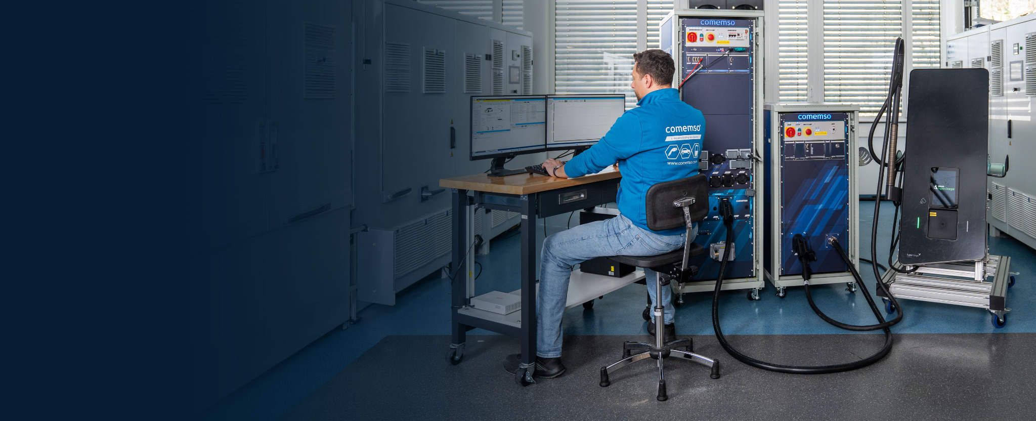
Applications / EVSE Testing
EVSE testing with controlled vehicle behaviour
Validate electric vehicle supply equipment (EVSE) with a controlled vehicle simulation. Repeat normal charging sessions, vary defined conditions and compare the station response before and after a software update.
EVSE testing: controller, complete charging station and real EV–EVSE pair
Define the vehicle behaviour, electrical fault cases and reports needed for the next project. Then check how the test setup can support new charging functions and higher power, and select the system configuration.
For an observed real EV–EVSE failure, keep passive observation separate from a simulated counterpart. A common time base helps inspect the captured signals; it does not by itself prove causation.
| Real device under test | Charging partner | Test task and system |
|---|---|---|
| Charging controller (SECC) | Simulated EV communication at the controller interface. | Check messages, states and timing with EVCA ComOnly and the configured Core. Controller communication testing alone does not verify a complete power path. |
| Complete charging station (EVSE) | Simulated EV, with the required power and load hardware. | Correlate charging requests, signals and electrical response with EVCA Flex and configured Test Libraries. Source, load, fault and operating limits belong to the selected setup. |
| Real EV–EVSE pair | Real vehicle connected to the real charging station. | Investigate an observed interoperability issue with EVCA Interop. Capture communication and charging measurements on one timeline; passive observation does not replace controlled partner simulation. |
DC EVSE test example: response to a lower EV current request
Stimulus: During a controlled DC charging test, the EV simulation requests a lower charging current. Keep the selected voltage and other test conditions constant within the configured operating limits.
Expected response and evaluation: Compare the real charging station’s communicated response and measured current with the required reduction, ramp and timing for that test case. Align the EV request, EVSE messages and electrical measurements in comframe. Specify acceptance criteria from the applicable requirements and configured test scope before the run.
This is a test objective, not a reported measurement result.
Charging-process analysis · AC/DC commissioning and field service with Easy Chester Ultimate; AC installation testing with Easy Chester Micro
For your existing EVSE test bench
Compare three paths for your test bench
Assess an extension, additional equipment or a replacement using the same test cases and evidence required for the next EVSE release.
On smaller screens, scroll the table horizontally to see every column.
| Path | Consider it when | What to establish before deciding |
|---|---|---|
| Extend | The existing architecture can support the additional functions, interfaces or operating points. | Confirm the released upgrades, power and fault limits, and compatibility with the existing workflow. |
| Complement | The existing bench remains useful, but a specific test task needs additional equipment. | Specify the additional function and interfaces, assign safety responsibilities and agree how the combined results will be recorded. |
| Replace | The current architecture no longer covers the required test scope. | Demonstrate the required tests and daily workflow. Agree the configuration, integration, acceptance criteria and training needs. |
Anonymised project example · EVSE manufacturer
How an EVSE manufacturer chose three test systems
For an expansion of its test equipment, an EVSE manufacturer selected EVCA Multi Mobile, EVCA Flex with IEC 61851-23 test capability and EVCA MCS. According to comemso’s project account, the software workflow, demonstrated electrical test depth and confidence in the engineering partner drove the decision.
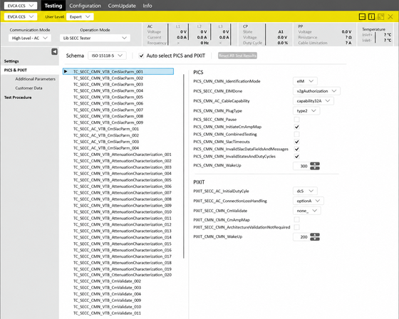
Software workflow and analysis
comframe combines automated analysis and Professional Simulation: compare measurements with configured expectations, then vary supported message values, timing and sequences. ISO 15118-4/-5 SECC TestLibs are released in comframe; their applicable cases depend on the software package and DUT.
Explore the comframe application workflow →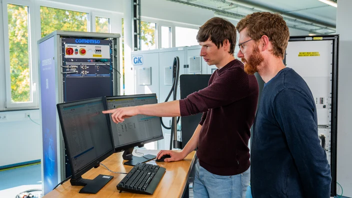
Electrical test depth on a customer’s charger
comemso demonstrated the full IEC 61851-23 Annex CC.7.5 test scope on a customer’s charging station in the matching Flex configuration. The demonstration used the existing IEC TestLib application software. Its port to comframe is not yet released.
Review the Flex test configuration →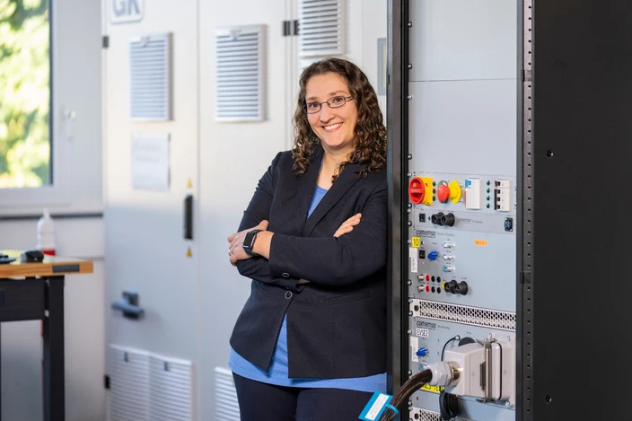
The people and facilities behind the system
During the site visit, the customer saw software development, electronics manufacturing, assembly, wiring and system testing. The project account describes how this strengthened its confidence in comemso as an engineering partner.
Explore development, manufacturing and testing →Source: comemso’s anonymised project account of the system selection. Images illustrate the software and test environment.
Use these criteria to assess your own test bench
Agree your DUT, standard edition, test cases and operating points. For electrical IEC testing, identify the released TestLib, required IEC rack, external load, oscilloscope and protection concept. Define integration responsibilities, acceptance criteria, report scope and training needs for your configuration.
Discuss your EVSE configuration and demonstrationFollow the charging station through its lifecycle
EVSE test tasks from development to commissioning and service
Find the relevant product families for seven areas of the EVSE lifecycle.
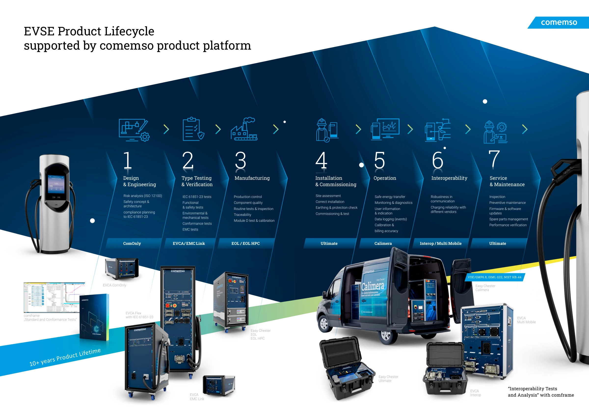
10+ years in the life of a charging station
Development, verification, manufacturing, operation and service each call for different tests. Select the system for the task at hand.
Find the system for your test task
Open each test area to view its tasks and products.
Design & engineering
Develop and test EVSE communication and control functions before the complete high-power system is available.
Type testing & verification
Investigate conformance, electrical behaviour, safety functions and EMC with a setup matched to the required tests.
Manufacturing
Turn validated requirements into repeatable end-of-line tests with reports and traceability.
Installation & commissioning
Before handing over an installed charging station, check electrical protective measures, communication and charging function. Use Easy Chester Micro for AC installation testing, or Easy Chester Ultimate when the task also includes DC charging.
Operation
Verify energy measurement and billing accuracy under field conditions.
Interoperability
Investigate charging reliability and communication across vehicles and charging stations from different manufacturers.
Service & maintenance
Repeat electrical safety and charging-function checks after repairs and during periodic inspection. Use Easy Chester Micro for AC site work or Easy Chester Ultimate for AC and DC.
Set the EVSE test scope
Test the charging station with a controlled vehicle simulation
EVSE testing checks the electrical, functional and communication behaviour of electric vehicle supply equipment. The system simulates the EV side to create repeatable normal, boundary and fault conditions. Match the test depth to the controller, complete charger, production line or installed station you need to assess.
Development and laboratory validation
Test SECC communication, EV simulation, low-level signals, protocol timing, conformance, robustness, power, safety and faults before field deployment.
EVCA ComOnly, EVCA Flex and Test LibrariesManufacturing and end-of-line
Before each station leaves production, verify parameters, charging function, communication, electrical behaviour and safety-relevant outputs. Include automation and traceability in the production test.
Easy Chester EOL, EOL HPC, EVCA and comframeInstallation, operation and service
Check installation, protective measures and charging function on site. Record the results of commissioning, billing-accuracy checks, repairs and recurring inspection.
Easy Chester Ultimate and Calimera
EU regulation and market access
AFIR connects communication readiness, interoperability and operational evidence.
AFIR is broader than one protocol test. For EVSE development, the technical transition includes continued ISO 15118-2 support and growing ISO 15118-20 readiness, while deployment also requires separate attention to payment, pricing, backend connectivity and data obligations.
Communication readiness
Verify current ISO 15118-2 behaviour and prepare the SECC hardware and software for the required ISO 15118-20 scope.
Coexistence and Plug & Charge
Plan the public charging infrastructure so legacy and newer vehicle implementations remain supportable.
Lifecycle evidence
Combine conformance, interoperability, power, fault reactions, commissioning and field verification instead of treating readiness as one pass/fail test.
Scope boundary
Payment certification, legal assessment, pricing transparency, backend connectivity and data obligations remain separate responsibilities.
Analyse the charging process
Trace the charging process to the first inconsistency
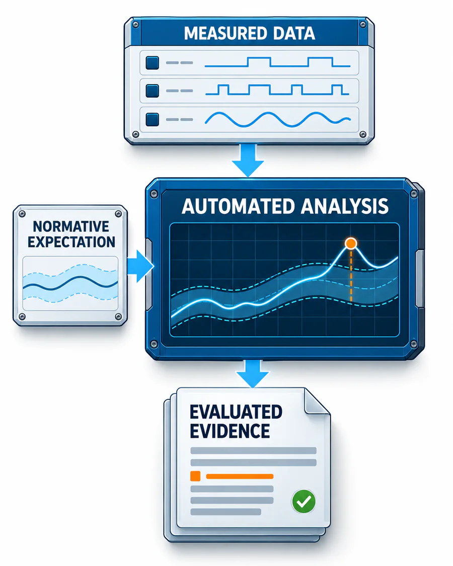 View the analysis diagram at full size
Reusable configurations, campaigns, reports and traceability.
Battery requests, connection states, Control Pilot (CP), Proximity Pilot (PP) and technology-specific low-level signals.
DIN 70121, ISO 15118, CHAdeMO, GB/T and MCS according to scope.
Message content, sequences, timeouts, optional paths and deliberately incorrect behaviour.
Requested and measured voltage, current, power, ramps and shutdown.
Protective functions and reactions to electrical, signal and communication faults.
EVCA Interop and Charge Playback
Repeat real vehicle behaviour in the EVSE laboratory test
EVCA Interop captures a real EV-to-EVSE interaction, including issues specific to one vehicle implementation. Charge Playback uses supported EV-side PLC (power line communication) content and timing to act as a physical charging partner for the EVSE under test.
- Real charging session
Connect the charging station to the vehicle involved in the reported interoperability case and reproduce the relevant site condition.
- Record
Capture the EV-side PLC content, timing and related charging measurements from the real session.
- Extract
Select the recorded behaviour supported by the EV simulation configuration and retain the source session.
- Active simulation
Apply the recorded vehicle behaviour to the EVSE through its physical charging interface.
- Repeat and modify
Repeat the charging-station test, changing one vehicle-side condition at a time. Reuse the observed EVSE response in automated regression tests.
Analyse the real charging pair
Use EVCA Interop to investigate the charging station with a real vehicle. Choose a configured EVCA Multi Mobile system when the task also needs broader portable measurement and vehicle-side charging-partner simulation.
Explore EVCA InteropSimulate the recorded vehicle behaviour
Use released Charge Playback functions to repeat recorded vehicle-side behaviour at the EVSE’s physical charging interface.
Explore Charge PlaybackCharging technologies and standards
EVSE charging interfaces: AC, DC CCS / NACS, CHAdeMO, GB/T and MCS
Select communication, low-level signals, power hardware, Test Libraries and released functions for the charging technology being tested. Check the exact standard editions and product scope.
AC charging
IEC 61851-1, SAE J1772 and ISO 15118 where applicable, with CP and PP simulation and functional testing.
DC CCS and NACS
IEC 61851-23, DIN 70121, ISO 15118-2, ISO 15118-3 and ISO 15118-20 according to configuration.
CHAdeMO
EV simulation, CAN communication, low-level behaviour and functional workflows for supported versions.
DC China / GB/T
GB/T 18487.1 and GB/T 27930 variants with technology-specific communication and state evaluation.
Megawatt Charging
10BASE-T1S, ISO 15118-20, CE and ID, auxiliary supply, temperature, cooling and high-power architecture.
IEC 61851-23 electrical test coverage, conformance profiles and high-power fault cases require the corresponding system hardware and released Test Library scope.
EVSE test equipment by lifecycle stage
EVSE test equipment: laboratory, production, commissioning and service
Compare systems by lifecycle stage, hardware, ratings, interfaces and the released functions needed for your test.
EV simulation, protocol analysis and communication development on a bench without full-power equipment.
Communication, signals, power integration, fault simulation, conformance and automation.
Portable multi-standard measurement and simulation for validation and field work.
Real EV-to-EVSE capture, synchronised evidence and field-to-laboratory transfer.
Dedicated MCS communication, signals, cooling and high-power architecture.
EMC testingTransparent optical charging communication across the EMC chamber boundary.
ProductionRepeatable manufacturing tests with functional checks, parameter verification and traceable results.
Production and high-power end-of-line workflows with project-specific integration.
Compact AC installation tester for commissioning, electrical safety, maintenance and periodic inspection.
AC/DC installation tester for commissioning, electrical safety and charging-function checks, with guided reporting for maintenance and service.
Mobile on-site calibration and metrology-related verification.
Software and evidenceConfigure tests, analyse synchronised data, automate sequences, report results and integrate the setup.
Defined test cases, standard editions, DUT roles, verdicts and evidence.
Customer references
Proven in development, certification and real-world EVSE testing.

“We ensure high-quality test results with the right test equipment”

“Thanks to the use of your equipment, we have achieved excellent results in our validation and certification process. Their quality and performance have exceeded our expectations.”
Validate supplied EVSEs before release
Operators and integrators need test records for new suppliers and for hardware or firmware changes. Use repeatable Easy Chester reference service checks alongside deeper EVCA laboratory qualification, with a defined scope for each.
Frequently asked questions
EVSE testing
What is EVSE testing?
EVSE testing verifies the electrical, functional and communication behaviour of a charging station. The EVSE is the device under test, while the system represents the vehicle side and creates controlled conditions.
What is the difference between EV testing and EVSE testing?
During EVSE testing, the charger is the device under test and the system simulates a vehicle. During EV testing, the vehicle or EVCC (vehicle-side charging communication controller) is the device under test and the system simulates a charging station.
Can a charging station be tested without a real vehicle?
Yes. An EV simulator can reproduce low-level states and high-level charging communication. Depending on the test scope, it can coordinate a battery emulator or load for repeatable power testing.
What is the difference between a compact EVSE tester and a laboratory system?
A compact EVSE tester guides defined function, safety, commissioning and service checks. A configured laboratory system provides additional protocol-conformance and robustness tests, power equipment, fault injection, automation and synchronised analysis.
How does EVCA Interop support EVSE testing?
EVCA Interop records the interaction of a real charging station and vehicle, aligning the relevant technical layers on one time base. This makes vehicle-specific issues visible that may not appear with a single simulated partner.
What is the difference between conformance and interoperability?
Conformance testing verifies one implementation against defined requirements and test cases. Interoperability testing investigates how two concrete implementations behave together in a real charging session.
What are the best tools for testing EV charging stations?
Select the tools for the test task. A suitably configured Easy Chester guides commissioning, maintenance and repair checks. An EVCA laboratory system provides the selected EV simulation, power equipment, fault insertion and synchronised communication and electrical analysis.
Use real EV-to-EVSE measurements for interoperability investigations, and the appropriate configurations for production and calibration. Compare connector and protocol coverage, electrical limits, safety and fault functions, measurement records and reporting.
| Test task | Starting point | What the setup should provide |
|---|---|---|
| Commissioning and field diagnosis | Easy Chester Ultimate | Configured charging, safety and fault checks with a documented field result |
| Controlled laboratory validation | EVCA | Selected EV simulation, interfaces, power equipment and repeatable test conditions |
| A failed real vehicle–station combination | EVCA Interop | Synchronised communication and electrical measurements of the real pair |
| Repeatable production acceptance | Easy Chester EOL | Released test sequence, unit identity, limits and a result for each station |
| Verification of delivered charging energy | Easy Chester Calimera | Controlled real load, suitable reference meter and the applicable metrology procedure |
For the specific device under test, confirm connector coverage, electrical range, released software functions and the required test procedure for the chosen configuration.
Compare Easy Chester field and production paths · Compare EVCA laboratory and analysis paths
Charging-station test planning
Plan charging-station validation
Define the EVSE development stage, vehicle behaviour, communication checks and electrical fault cases. Select the test system and power equipment against these requirements.