
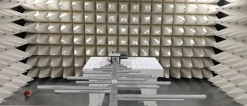
EMC Link for EV and EVSE testing in the EMC chamber
Observe charging-system behaviour while electromagnetic interference is applied to the DUT.
EMC Link carries charging signals and communication over optical fibre through the EMC chamber boundary. For a vehicle-side DUT, a compatible EVCA test system simulates EVSE (electric vehicle supply equipment, or charging station). For an EVSE-side DUT, it provides EV simulation.
Place the compact unit beside the DUT and use the connected test system outside the chamber for millisecond-level signal analysis.
Signal access during the EMC test
- Acquire charging-signal data during active EMC exposure using the connected test equipment
- Integrate the compact chamber-side unit into the available space beside the DUT
- Connect optically to a compatible comemso test system for EV or EVSE simulation
Connect the charging counterpart outside the chamber
Keep the DUT in the chamber and connect its simulated charging counterpart outside. Use this arrangement to observe charging responses during conducted emissions testing and other EMC tests in the planned laboratory setup.
- Automotive EMC testing. Optically separate the charging-signal connection for EV or EVSE tests during radiated immunity and emissions testing
- Transparent communication. Transmit the configured charging signal paths and protocol communication between DUT and test system
- Chamber integration. Plan fibre routing, feedthroughs and the filtered supply as part of the laboratory setup
Two optical fibre cables connect the chamber-side and external units. The setup described here uses a filtered 12 V DC supply for the chamber-side EMC Link unit, with approx. 2.5 A input current.
Plan the chamber connection
Define the DUT, charging technology and signal paths for your anechoic-chamber setup.
Discuss module selection, feedthroughs and the connected test system with comemso application engineering.