
Charging interoperability analysis
Find out why a vehicle and a charger don't work together.
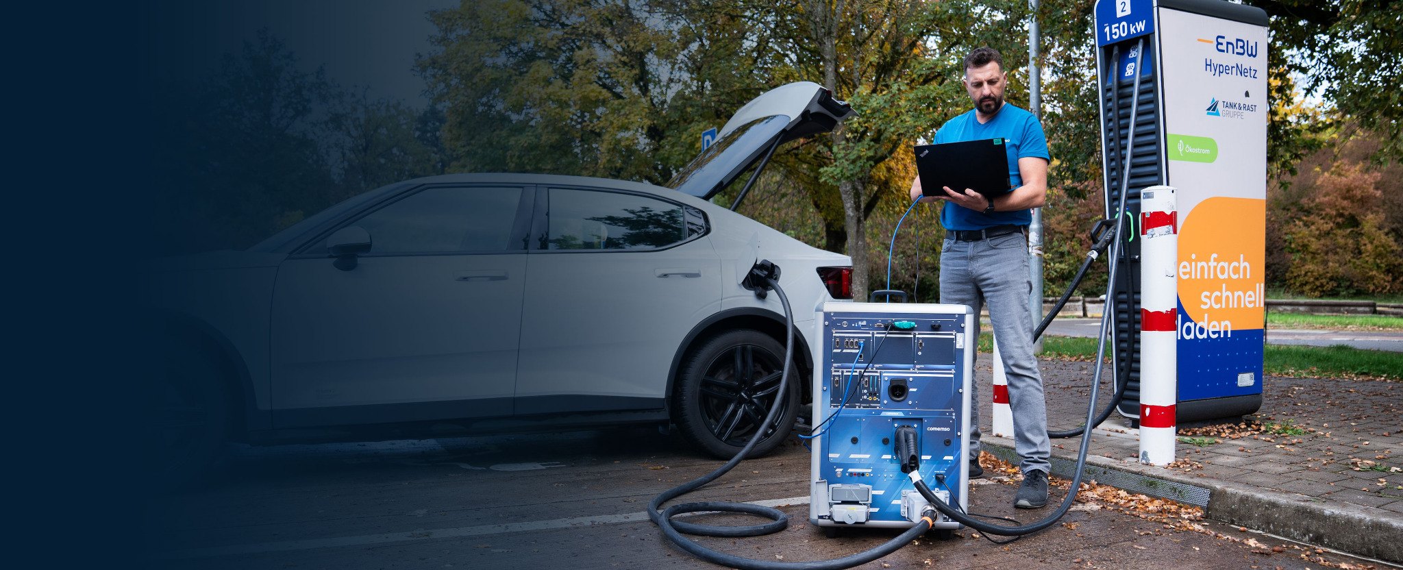
EVCA records messages, voltage and current of the real vehicle and the real station on one timeline, shows the first deviation and lets you confirm the cause by simulation – instead of swapping parts until the fault disappears.1
One EVSE manufacturer had searched for seven months. The recording pointed to the precharge response; the analysis took about three minutes.
- What for
- Teams who must find out why a specific vehicle and charger don’t work together.
- What it does
- Messages, voltage and current of the real pair on one timeline; a seven-month search ended after about three minutes of analysis.
- Not for
- Release testing of a single product against the standard – that is EVSE testing or EV testing.
Every unexplained charging failure leaves a driver at the station – and sends a ticket to your support team.
The interoperability investigation, planned
Start with the real charging pair.
First, you identify the EV and EVSE involved. The documented diagnosis case shows the method; the measurements follow what your charging pair needs.
Test scenario: Start with the precharge mismatch
In the documented customer case, the voltage requested by the vehicle did not match the charging station’s measured precharge response. Precharge prepares the voltage before the main power connection closes. The test compares request, measured voltage and next state together; after you correct the control parameters, the charging attempt runs again.
Compare the timing with the measured voltage.
In an anonymised EVSE (electric vehicle supply equipment, or charging station) case, the requested battery voltage and measured precharge response did not match. Reviewing communication and electrical signals together made the mismatch visible.
Tracing charging interoperability failures
Bring vehicle and charging-station records onto one timeline.
Charging failure analysis follows the sequence across communication, low-level control and electrical behaviour. Separate PCAP files, vehicle logs and charger traces may show the final error while leaving the first deviation unclear.
Vehicle, charging station, backend and laboratory tools often use different time bases. When records are aligned manually, the apparent order of events can change.
You check decoded messages against low-level states, voltage, current and the expected charging phase. Messages alone cannot show that these stayed consistent.
The same conditions test the suspected cause before any software changes. This gives both teams a basis for discussing symptoms that appeared in separate exports.

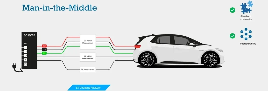
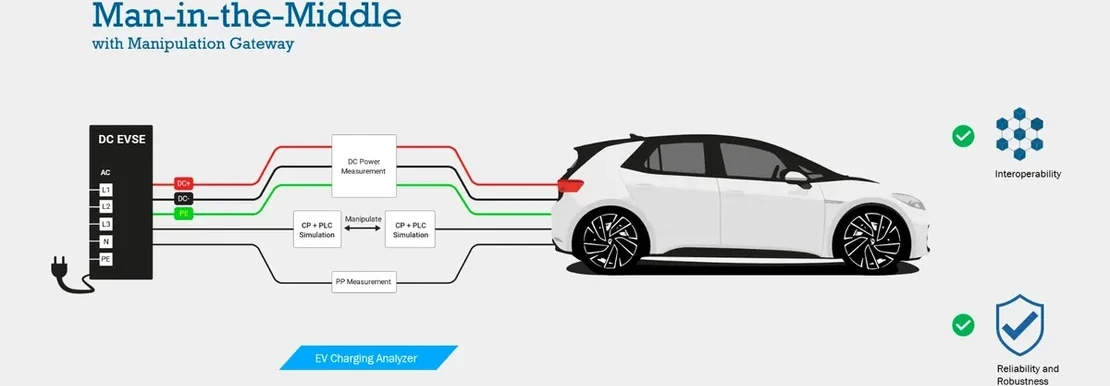
Passive Man-in-the-Middle measurement
Record the real vehicle and charging station together.
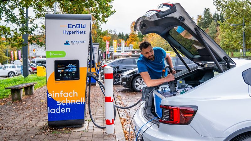
Passive Man-in-the-Middle measurement records the relevant layers at the physical charging interface on one time base. Both real partners stay connected, so the interaction that produced the problem is preserved.
First you record the real event, then you confirm the cause – by changing the live session or by simulation in the lab.
Cross-layer charging analysis
Check the charging process across messages and measurements.
Charging interoperability analysis compares protocol messages, timing, low-level states, voltage, current and both partners’ reactions. Reviewed against the charging phase, they reveal the first technically meaningful deviation.
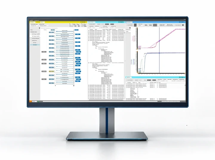
- 1Partner request: charging-message sequence.
- 2Device response: synchronised voltage and current traces.
- 3Result record: decoded messages and event data.
Messages, states and measurements are checked for agreement.
Message direction, sequence, content and timing.
Connection, control, signaling and stop conditions.
Voltage, current, power transition and physical reaction.
Charging phase, permitted combination and identified deviation.
Automated Standards Analysis can add normative or configured expectations where released. Cross-Layer State Monitoring is implemented for applicable DC CCS, CHAdeMO and DC China / GB/T DC configurations.
One charging interoperability method
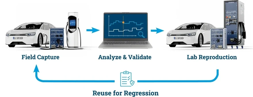
CCS interoperability testing: from failed charge to root cause
- 1Connect
Connect to the real EV and EVSE at the charging interface.
- 2Capture
Capture the relevant charging layers on one synchronised time base.
- 3Decode
Decode messages and identify state transitions, signals and timing.
- 4Correlate
Compare communication with low-level signals and electrical behaviour.
- 5Analyse
Find the first deviation from the expected charging state.
- 6Validate
Change one controlled condition to test the suspected cause.
- 7Reproduce
Reproduce supported partner behaviour in a repeatable laboratory test.
- 8Reuse
Keep the case for supplier discussions, regression tests and documentation.
The cause validated, the field case reproduced
Check cause and effect before changing the product.
Once the first deviation is isolated, change one condition to test its effect. The live gateway keeps both real partners connected.
Both real partners stay connected during the test
Where released, Manipulating Gateway shows whether a selected value, message or timing condition changes the result.
Manipulating GatewayThe partner behaviour, repeated in the laboratory
Where released, Charge Playback presents recorded EV-side or EVSE-side behaviour to the device under test again.
Charge Playback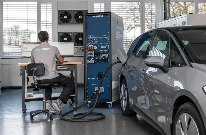
Recording and test conditions stay together
Record the case, repeat the conditions and verify the correction.
Save the synchronised measurement with the expected behaviour, observed deviation, validation condition and decision. The link to the original event stays, so others can follow how you reached the conclusion.
- Communication and measurements on one synchronised time base
- Expected state, observed behaviour and deviation shown together
- Documented conditions for the controlled validation test
- Shared records for development, suppliers and laboratories
- A reusable case for release regression and variant testing

Use the same case in development, supplier discussions and field support.
Where to use charging interoperability analysis
Resolve integration failures before release
You investigate the interaction while changes to vehicle and charging-station software can still be planned and tested.
The charging pair, recorded on site
You capture the event while both implementations are still on site and their original interaction is observable.
Give both teams the same recording
Vehicle and charging-station teams review the same time base, event sequence and tested hypothesis.
Verified cases repeated after updates
The relevant partner behaviour repeats after software, parameter or hardware changes.
Choose the next test step.
From method to implementation
Next tasks: record a real charging pair, reproduce partner behaviour, configure faults or select a complete test system.
EVCA Interop records communication and measured signals from the real vehicle and charging-station pair.
Broader portable measurement, simulation and multi-standard field work.
See the released standards-aware evaluation and timing analysis functions, with examples from the user interface.
Supported live changes, protocol scope, limits and validation conditions.
CapabilityActive physical charging-partner reproduction, direction and release depth.
Defined test cases, standard editions, DUT roles, verdicts and validation scope.
Conformance, interoperability and robustness
Choose the test discipline for the question.
Conformance
Does one implementation meet a defined requirement set and standardized test cases?
Interoperability
How do two specific implementations work together during a real charging session?
Robustness
How does an implementation respond to configured limits, timing changes and difficult partner behaviour?
Frequently asked questions
Interoperability and charging analysis
What is charging interoperability testing?
Charging interoperability testing examines a specific real EV and EVSE during a charging session. It compares communication, low-level states, timing, electrical behaviour and both implementations’ reactions.
How does interoperability differ from conformance testing?
Conformance testing checks one implementation against defined requirements and test cases. Interoperability testing checks how two specific implementations interact. Both are needed to answer these different questions.
Why can individually compliant products still fail together?
Interpretations, optional behaviour, timing margins, certificate conditions, state transitions and error handling can differ. Their interaction may reveal a problem that a test of either implementation alone did not show.
Why is passive Man-in-the-Middle measurement useful?
Both real partners remain connected during the field capture. Passive Man-in-the-Middle measurement records the relevant layers on a common time base and preserves their actual interaction.
Why can communication traces alone miss an EV charging fault?
Compare a communication trace with measured voltage and current to check whether the electrical response matches the requested values. The trace alone cannot establish that match.
In the anonymised comemso precharge case, communication timing appeared unremarkable, while the measured EVSE voltage response did not match the requested battery voltage. An experienced product specialist identified this relationship by reviewing synchronised electrical and communication recordings. This was human analysis of one vehicle–charger pairing; the account does not establish that all faults have the same cause or diagnosis time.
Can a suspected cause be tested before software is changed?
Yes, where a released live validation method supports the required controlled change. The purpose is to observe cause and effect before implementing a correction in the EV or charging station.
Customer projects, success stories and technical articles related to this page.
- Customer projectCharging Interoperability: EV Manufacturer, March 2026A returning vehicle manufacturer expands AC and DC CCS charging interoperability tests with EVCA, building on its existing test workflow.
- Customer projectEVCA Multi Mobile in the Field, April 2025EVCA Multi Mobile combines AC and DC CCS charging tests with customer resistive-load equipment for mobile EVSE testing. Project report, April 2025.
- Customer projectPortable CCS EVSE TesterCustom EV Charging Analyzer/Simulator in a compact transport case for mobile EVSE development, CCS communication testing and diagnostics.
- Product newsEVCA Multi Mobile Generation 5: Launch 2024EVCA Multi Mobile Generation 5: modular Flex architecture introduced in March 2024, with replaceable modules for repairs and hardware extensions.